Getting Around

Why am I doing this?
To help unlock the potential of Revit Structure in less time, because time is money. Plain and Simple

Friday, July 23, 2010

Linework

Hadn't used linework until now.

Basically, you can change the way the lines look on your screen/sheet.  This applies to model and detail elements.  Im not sure what all the rules are, but I have been looking for a solution to hiding some hidden grade beam lines for weeks and this was an easy fix.  Can't say that often.
This is the corner of a slab on grade with a grade beam, for some reason revit shows the hidden intersection line.  That's dumb.  So how do I get rid of it?   


You have to select an item on the screen before the linework tab appears.  You can then change lines to a different linestyle.  Here I will choose Invisible lines so that they will go away
All better

It also allows you to hide or change lines in section view.  When the model elements just aren't quite the way you want them, you can change the linework and hide them but they are still available to keynote.

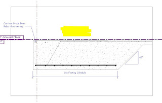
This is a PEMB footing attached to the slab.  This is what the model elements look like without modification.  We'd like to show the 45 degree chamfer of the footing edge to the slab.  How do we do that?
That looks better, I hid the elements and drew a concrete region.  Oh wait, where did my spot elevation and slab keynote go?  When you hide the elements all keynotes, elevations, etc. go away to.  What now?
Now, that's how we want it.  You use the linework detail and change the lines to invisible.  This keeps our dimensions, elevations and keynotes for our model elements.
You really want to use regions as little as possible, but in this situation, it is SO much easier and faster just to draw the region and move on with little consequence to the integrity of the model. 

Monday, July 19, 2010

Inserting or Linking CAD drawings into Revit.....a focus on viewing options

When you insert or link a CAD drawing into Revit, a key option is the checkbox INSERT INTO CURRENT VIEW ONLY.  This will give you the option to move the reference in front of or behind your Revit elements.  Very helpful.  If you don't check the box, this option is unavailable.

The CURRENT VIEW ONLY checkbox is on the left.  Another option is the COLORS, I like to choose (Preserve) from the pulldown instead of (Black and White) because it will look just like the file you are about to insert.
When inserted into CURRENT VIEW ONLY several addtional options are available.  The pulldown on the left allows you to bring the inserted/linked cad drawing in front of the revit model (foreground) or bring the revit model in front (background).  This is similar to isolate layers/hide xref in autocad.  On the right side you can SEND TO BACK or BRING TO FRONT. I really haven't used these options yet in this tab and haven't figured out when to use it.  Maybe when multiple items are linked or inserted?
FOREGROUND
BACKGROUND

Sunday, July 18, 2010

Getting Things Done: The Simple Dollar Part I

The Simple Dollar � Getting Things Done: A New Practice for a New Reality

This is a 14 part series on the book Getting Things Done by David Allen. I've found this is an effective way of applying organization to our crazy lives. The website it comes from: The Simple Dollar is a fantastic blog worth checking out everyday.

The Simple Dollar

Changing Grid Letters/Numbers and Section Numbers

You know, Revit will name/number the grids for you and wont let you have more one of each letter.  This is all well and good, but what happens when you need to add a column line in between.  From what I know as of right now, a total pain in the fucking ass happens.  Well, sorta, and I guess I have come to expect so much automation from revit that this seems like it should have been handled. 

If you have grids A-F and you want to add a grid between D & C, well you can't just name it D and start renaming from there because Revit will only allow one instance of each letter.  Also, it will name the new grid G.  Same thing for section numbers on detail sheets.  If you add another section between section 3 & section 4  same deal.

The best way to handle this is start at the end and work your way back. First you have to name the new grid something crazy like X or something because you will change your F grid to G, then E to F, then D to E, then your new grid from X to D.

After cussing several times, it's just easier to start at the end and work back, but when you are adding several grids at different locations, it makes it even more cumbersome

I guess I just expect more from Revit.  Is it so hard to ask me when I put in a grid if I want to rename all of the following grids? As the say on NFL primetime "C'MON MAN"!!!!!!!!!!!!

Somebody tell me Im a dumbass and there is a better way to do this or Autodesk fix this or tell me why you wont.

Funny, after writing this I found an extension by Avatec Utilities that takes care of this.  Im not sure if it's part of their free download or not, but Im going to try it out.

Tuesday, July 13, 2010

Converting CAD details to Revit Details

Fear and Loathing In a CAD vs. BIM World: Converting CAD Details To Revit Details: Just Do It...One way or another.

This is a really good guide for changing a cad detail into a revit one. You just have to do it, and doing it as we go is the only way.

MASKING REGION & FILLED REGION

We use these two commands a good bit, I think less and less as we get better and that is a good thing.  Let me explain a little.  If you draw it correctly in the model, you don't have to use these two commands to hatch the area, therefore completely elimating the step of actually typing the command and having to draw the area.  Big plus from a time standpoint.

These commands essentially are self explanatory.  Its not difficult to use the commands without any thought.  However, there are a few tips and tricks in using them.
  • You use these most of the time to hide you model components in 2D detailing. This happens to me quite often as I can't make everything look correctly in 3D, it happens less and less but it still happens.  For example, when you have a slab, turndown and footing, these are 3 seperate model elements and take some work to make look correct.  So you have to hide them.  This creates two time sucks.
    • First, you have to draw your region and adjust the type to make it look correct
    • Two, Keynotes do not show up when the elements are hidden, therefore your automatic noting goes away.
  • There are a couple of items to be aware of when you are executing the command. 
    • After executing the FILLED REGION command, you will have access to the (Create Filled Region) Tab.  On the right side, the line style controls the type of line for the outline of the region.
    • To change the type of fill, in the (Properties Palette) you have to execute EDIT TYPE, then select whatever pattern from the TYPE pulldown.  WTF autodesk??? Why isn't it in the (Properties Palette)
    • After executing teh EDIT TYPE command in the (Properties Palette) you can create a new type of region by DUPLICATE and renaming.  Fill pattern may be selected from the library, it can be opaque or transparent, the weight and color can be changed as well. 
I used filled region mostly, because I can make it transparent or opaque, but maybe Im missing a good use for masking region. 

When selecting the fill pattern, designate model or drafing in the radio button.  Of course drafting is 2D and model is 3D, but the drafting pattern gives you more material options.

That's about all I can think of right now.  If there's anybody out there, let me know if you have anything to add or correct.  Oh, I'll add some pretty pictures later, but for now it is what it is

Exporting to Autocad: The PCP file

revit in plain english: Revit PCP Files

Revit creates a pcp file whenever you export to CAD, this article explains a little how to manipulate it.

Wednesday, July 7, 2010

PROPOGATING EXTENTS

To transfer your column line modifications, such as length and spacing of the heads so they match, and turning symbols on and off to other views; you can use the Propagating Extents button.

There are some random problems with this tool.  So if you run into problems with it not working like you think it should.  Check out the Mastering Revit Book for some solutions.

Monday, July 5, 2010

Using Design Phases in Revit Drawings

Using Design Phase in Your Revit Project | CAD Notes

I haven't read this one yet, but have used phases on a Revit project and it didn't seem too difficult, although I just used the arch's existing elements and did not create my own

Creating Title Block From AutoCAD Sheet

Creating Title Block From AutoCAD Sheet | CAD Notes

He said it, so I don't have to

Saturday, July 3, 2010

Change Beam System Levels

When you select a beam that's part of a beam system or if you select the beam system itself; the Reference Level and Work Plane option are grayed out.


To remedy this:

Once the beam is selected, click the edit workplane button on the ribbon, then specify your new workplane by choosing a level from the pulldown or selecting a line from a view.  I haven't used the last two options so Im not sure what they do :)

Friday, July 2, 2010

Revit Structure 2011 User Guide

Autodesk - Autodesk Revit Structure Services & Support - User's Guide

Here's a link to the user's guide. It's not hard to find, but it should be easier to access. So here you go.

Thursday, July 1, 2010

The Best, the Rest, the Rare: 100 AutoCAD Tips You Should Know


The Best, the Rest, the Rare: 100 AutoCAD Tips You Should Know | CAD Notes


Not Revit, but some useful CAD tips

Revit Keyboard Shortcuts

Modifying your keyboard shortcuts is really simple. I've found keyboard shortcuts are one of the best ways to improve your efficiency in revit.

Under the view tab, at the end is the User Interface Button, click it and at the bottom of the pulldown is the keyboard shortcuts. Once you open that you can modify any command.