Getting Around

Why am I doing this?
To help unlock the potential of Revit Structure in less time, because time is money. Plain and Simple

Tuesday, December 27, 2011

Drag and Drop Families

Sometimes the most obvious answer evades you, this is probably one of those times.  Loading families into your drawings can be one of the most time consuming aspects of completing your project.  Well, this little tidbit jumped up and bit me today.

You can drag and drop families into Revit from windows explorer.  Yes, i know, Im an idiot, but just in case your an idiot like me, now you know.  

There are some limitations it seems.  It will only pull the one type into your project, and it seems to be a some sort of default type, because it is random to each family.  Im sure some more experimentation will reveal some more answers, but that's where Im at with it.

So now you know and as GI Joe taught us "Knowing is Half the Battle"


Sounds like some "contractors" I've worked with.  "I built it in two weeks and I never bothered to look at the structural engineering drawings!"

I thought it looked like a pretty good design though, he had the kickers.  Although the railing was a bit on the weak side, it didn't appear to meet the 42" min  requirement.  I will say the (4)10d nails that attached the railing should be adequate, unless you need them to resist pullout to save your life because you are hanging by the railing........I digress

Tuesday, November 8, 2011

What Revit Wants: 3 Ways to Add Multi-Line text to Revit labels

What Revit Wants: 3 Ways to Add Multi-Line text to Revit labels: Many people know that you can add a carriage return (and thus create multi-line labels) in Revit by accessing a Properties entry box and hit...

I could not get cntrl+enter to work for keynotes, but the last two do work. Thank you, finally got this one. Should go a long way to improve the look of our notes

Wednesday, October 26, 2011

Revit to Tekla

Tekla has introduced a Revit to Tekla link free of charge

Haven't been able to try it out yet, but Im pretty sure this is light years ahead of what I was trying to do last year, although that was CIS/2 format.

There is a webinar on the topic, the first 15 mins are useful for Revit users, the rest, although it appears very good, is strictly for the Tekla user.

Here it is.....

The best MTV commercials ever, don't know why i thought about.  Maybe the fact they are bringing Beavis and Butthead back on tv.


Saturday, October 22, 2011

Using MODEL->IN PLACE->SWEEPS

Coming from a strictly 2D drawing platform has taken me some time to understand how to understand and control the 3D model.  Being able to under stand reference planes and In-Place Models is the key to being able to customize and create custom model elements and can often be more effective and faster when completed in the model rather than with detail components.  So there's why....Here's how

Ive drawn a concrete wall and slab. Im going to add a grade beam with a brick ledge and add some features to the wall.  Can you schedule this items as well.......I haven't figured out how yet

So we get started with the grade beam.  First off we need to see the grade beam in section in order to draw it most effectively so we will create a section cut.  (You want to place this cut close to the center of one of the lines you will pick for the path of the sweep, I'll show you why shortly).  


From MODEL->IN-PLACE we choose "Structural Foundations" option so that it should show in a schedule.  Name it "12x24 GB" or whatever naming system you use.


Since we are going to pull the grade beam around the edge of the slab we will use a SWEEP.  Choose the lines which will determine the path of the sweep.  Think about this as the path not the location of the model, since you can draw your element 100' away if you would like.  Notice the red dot at the middle of the first line you chose for your sweep path.  Right where we cut our section.  Had that dot not been in our view range of the section we could have drawn it, but not seen what we were drawing.  That is why I discussed the placement of the section.  You can do it without the section, but this is the best and most efficient way for me.

Now we are going to EDIT PROFILE.  It will ask you what plan,section, elevation you will use to draft the profile of the sweep.  We will use our section and beginning drawing the outline of the grade beam with a 8"x5" brick ledge.

After we have drawn the profile we will pick the material for the sweep.  This will matter for not only appearance, but possibly for schedules and joining of elements.

We will FINISH the sweep and FINISH the model.......and we have a grade beam with our brick ledge around the perimeter of the building.

And there you go.  Well, Im cashed.  Im old and tired.  So I'll do the rest of it later.....


Monday, October 10, 2011

Legends: An overview

Ouch...2 1/2 month lag between posts.  I have a TON of content for new posts, now to find the time.
Legends: An overview Good Article from Revit Zone about what else but......Legends

Tuesday, July 26, 2011

Editing HollowCore Slabs in Revit Structure

I did a project last year with hollowcore and had a difficult time customizing the hollowcore slabs.  I got it to work, but it was too hard and it had its limitations, and ultimately was not a 100% correct model.

First, understand that hollowcore slabs are considered beams, not slab elements (rightfully so).  Cutting a shaft or other floor modifications will not work.  


  • In Revit Structure 2012, Either I missed it before or it's new, but there it is, plain as day @: HOME tab/OPENING panel/BY FACE button.  Right next to shaft opening.  


  • After (or before) you open the command, go to a plan view showing your hollow core slabs
  • Select the top face of the hollowcore slab


  • Create openings as you would in a floor boundary command.  You may modify the end of slabs as reqd or cut a hole in the middle of the slabs.


Finish and your done.  Unless Im missing something, the only drawback or feature that is lacking is being able to apply this across multiple panels.  As shown below, the opening must be done in two steps, then you still have to put holes in you topping slab if you have one. It's understandable that it is not included in revit, but as a beam system this would be a nice option.


Modifying each individual plank is time consuming.  Honestly, on a large project especially, Im not sure the effort is worth the reward.  You can create the edges fairly quickly with linework.

You can create the same quality drawings while retaining most all of the benefits of revit, with minimal linework.  I doubt the schedules are affected by the modifications.

The picture above shows two elements which meet what I consider to be 100% BIM.  

The beam bearing detail at the top features the wall notch with the bearing plate
The lower detail is the previously discussed hollowcore and topping notch out
 I believe the rebar and the steel detailing would fall outside this description.  What do you think?


Monday, July 25, 2011

Revit Structure 2012 to AutoCAD Structural Detailing

Revit Structure 2012 to AutoCAD Structural Detailing Tutorial | Autodesk Revit Structure

Thanks to Lawrence H.  @  Revit Structure Blog.  There is a bunch of good info and tutorials there.

This is a really good article and tutorial about interfacing Revit Structure with Autocad Structural detailing. As a structural firm I think bringing these capabilities on would be helpful, and in limited applications, allow for production of shop drawings. The big question is, can we sell it?


Wednesday, July 20, 2011

Save down Revit File

zeeveld: Save down Revit file?

Here's a lifeline if you save your file in a newer version of revit and need to go back

Wednesday, July 13, 2011

THE Scope Box & THE Matchline

My coworker John was having to manually move the end of each column to the Matchline to "filter" the column lines to only show up on the same plan as the columns.  Time Killer right there, especially because the column lines have to be done individually in this case.

Im guilty of not filtering the column lines due to the time it takes to do this.  This is a Easy, Simple, and Clean way of doing it.  BOOM Free Money.  Even better, the Scope Box has a 3D element to it, exactly like a Section Box in 3D views.  Therefore you can apply the column line filtering over as many levels as you choose.

Enter Scope Box. Yes Friends.  The Scope Box does have a purpose.  Took a 3 day introductory Revit course in 2009.  I remember scope boxes, but the instructor didn't say this explicitly solved the problem or I just didn't grasp it at that point.  Anyway, let's see how it works.


Go to the VIEW Tab, Hit the SCOPE BOX button, you have to draw a box here.  Make sure you cut the scope box extents short of the CROP REGION of the plan.  It doesn't have anything to do with the matchline.  Just make sure the boundaries of the scope box and the crop region do not cross or the column lines will show up.


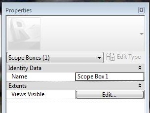
Now select the Scope Box, in the PROPERTIES box, you can give the scope box a name.  In our project, the side we drew our scope box on is Part "B".


Now we will repeat this for Part "A"


Lets go pick all the column lines which do not have a column in Part "B".  In the PROPERTIES Box, Assign them to Part "A" for the scope box.


Column line  A.1 Should not show up on my Part "B" Sheet or Plan.  You may have to adjust the crop region and the Scope Box sizes to get it to work correctly.  And we're out.

Killer.  No A.1 Column Line

Sunday, July 10, 2011

RISA & REVIT

STOKED to have picked up RISA capabilities at the office. Looks like we've swallowed the red pill.

Off we go, Im sure interoperability will become a mainstay (if there that exists yet) on the blog. Will it be a great duo or unmet expectations, time will tell....


Sunday, June 26, 2011

Schedules and Phasing

Did you know that all/most schedule are tied to phases seperately?  Make sure in the TYPE PROPERTIES when  in EDIT SCHEDULE screen; you choose the correct settings.  Otherwise you could be showing only one phase/alt, etc.

Nice (Should be a no brainer, but you never know with revit) that you can edit the schedules this way, although it's still another step to keep up with over the course of the project.

Off topic, but.....
Im not sure we're not headed for a touchscreen future in design, at least partially.  Have you ever used photoshop express, basically photoshop for tablets/smartphones?  Im terrible with photo editing but it's really a "natural" way to manipulate photos.  I wonder where we could take advantage of this in design?

Picture taken on a site visit with my EVO, then editing in photoshop express.


Tuesday, June 7, 2011

More than you need to know about Slide Bearing Plates!

751.11 Bearings - Engineering Policy Guide

Nice! Thank you internet.

On my trip to London, I couldn't help but admire the structure of terminal 5 at Heathrow.  I had a hard time figuring out how it works, but it is a beautiful use of structure.  Airports are becoming some of my favorite structures.


Thursday, April 14, 2011

Moving Forward: Revit Structure 2012

Revit is fairly easy and painless transition to update each year.  Here's a list of what options I changed in Revit 2012 to create the same workflow across updates

Big R Pulldown - Options Button - User Interface Tab - Keyboard Shorcuts - Import your previous year's file .xml
File Locations - Load your Default Template file .RTE
File Locations - User files - Your Revit Families Folder
File Locations - Family Template - You can use the default folder.  This is the new templates.  I have not changed any of the family template files personally.
File Locations - Places Button - Imperial Library File - Where your MODEL elements are located.  Under the structure folder
File Locations - Places Button (you change both of these files before leaving the same pop up menu) - Detail Library files are located (Think 2D)

That was about it for me.  Crude, but the info is there.

Tuesday, April 12, 2011

AutoCADWS for Android

AutoCADWS

Can I get a Hell Yes! AutoCAD on my phone!


Friday, April 1, 2011

User's Guide: Creating a Custom Elevation Tag

User's Guide: Creating a Custom Elevation Tag

Easy way to do it, but very random. Section cuts are in the same section as well.

Revit Truss Family Tips

Structural Revit Ninja: Structural Trusses with the Revit Truss Tool - Simple Truss

Project Browser Organization & Notes on Multiple Pages

Wanna organize your levels other than by name? Here it is.
VIEW tab ---- USER INTERFACE pulldown ----- BROWSER ORGANIZATION ----- NEW (name it whatever) ----- Group By - Type ----- Sort By - Associated Level - Decending (and whatever else you want to do with it in the pop up) ----- Ok, then make sure it is checked and then BOOM! levels are organized by height.

Want to put text notes on multiple sheets? Here it is.
VIEW tab ----- LEGENDS ------ make your note, then  pull it into a sheet from the browser.  Short and Suuuweeeeeeeeettt.

Monday, March 28, 2011

How to set default view in Windows Explorer

How to Enhance the View in Windows Explorer | eHow.com

If you haven't done this, you probably should.

Wish windows explorer would open with the correct width columns, with the last modified file at the top? Stuff like that?

Well, here is how you do it:

And Listen to this Song while you work:


Saturday, March 26, 2011

TEK screw Detail Component

Here's a TEK screw detail component I made.  It is NOT parametric.  However, you can select different types w/ keynotes and design values, but they will look the same.

Load Values shown as instance parameters for easy reference
Product Data catalog linked in Identity Data

What else should you add to a detail component like this?
Should you spend the time to make it parametric, or change with the size?

TEK screws

Wow! Well, still a long way to go, but SEC has a chance to run the table again, along with a NIT victory as well.


UPDATE: Neither happened, but strong showing for the SEC. Auburn can only get better.  I hope......

Sunday, February 20, 2011

Print Range - Visible portion of current window

Im sure this is dumb, there are other ways to to do this, and you've probably have done it before, BUT just wanted to give a heads up on one way to print exactly what you want, especially if you use a widescreen monitor.  In Autocad, you can specify a box selection to print.  That is not availble in Revit.  Just:  Current Window (Entire Sheet View) Visible Portion of current window (What you see is what you get) and Selected views.


Revit takes the "Visible Portion" very literally.  Thus, however you can cut and zoom your window is exactly what you are going to get.  Therefore "unmaximize your window, reshape it and zoom as needed and you are DONE!  You never know.

Structural Elevations Hidden Lines

Structural Revit Ninja: Structural Elevations Revisted:

This is a helpful tip when showing elevations. For us, this leans heavily on the tilt-up side. You want to be able to show your steel beyond the wall. This MAY be a way to do that.

Try it out.

Deleting Constraining Dimensions

REVIT Rocks !: REVIT Deleting Constraining Dimensions

Dennis and I ran across this issue when trying to move stuff around. It can get quite hairy to move big sections of items around. This can be one of the big issues though, just a quick read, but might save you some time one day.

Oh how I miss you stretch command. Please bring it to Revit, Autodesk.

Wednesday, February 9, 2011

Revit Structure - Orient to View

Structural Revit Ninja: Orient to View - Weird Revit:

A good explanation of a neat/sometimes useful way to manipulate the model

Tuesday, January 25, 2011

Revit to CIS/2

Is a horror show.  My building went to hell.  It is a known issue for autodesk, for a while and they have not fixed it.  Some of the extensions sound cool and kinda sorta work, but IMO they shouldn't release a half assed product and then offer little support and development of it.  Either include it and do it right or don't even introduce it.  Ok sorry, rant over.

I would like to point you to a good and FREE piece of software that I did come across in my adventures today. SteelVis from National Institute of Standards and Technology.  You can find it here.  The file will compile and display CIS/2 file.  The model is actually displayed in a web browser.  Just follow the directions given and you'll get to see and get a list of all your components and various info.


Maybe it's me, but Im finding the realities of BIM fall far short of the promises.  Don't get me wrong as the Auburn family says, Im "ALL IN" on Revit and BIM, but Im just finding it difficult to implement the full advantages.  Im sure it will get better with time, but as Capt Bob says there is a line between cutting edge and bleeding edge, unfortunately, we some of these issues are a knife to the juggular.  Oh, if you want to see where my building went on it's way from Revit to CIS/2, just check the vid, from Event Horizon. You've been warned.  


After the frustration, honestly, it's probably not this extreme.  It seems that stepped columns, Joist Girders and Joist give Revit the most difficulty.  The joist girders jumping up 20' on one end gave it a rather distorted view, thus my horror show correlation.  The data file is still somewhat correct and can be used as another broad quantity check. Most of the elements positions and types seem to be correct.  I have also sent a file, minus all the bar joists on the job.  I'll keep updating, as I sent a CIS/2 file, an IFC file, a SDNF file, and a DXF file to the detailer.  Im hoping something worked okay.  I will say this is my first attempt at this and I did not monitor my analytical model very closely.  I did work with it early on, so I should get somewhat correct results.  Any effort more than occasional tweaking is too much to be a time saver, plus the models seem disconnected.  Many of my analytical members have two lines, are crossed, etc.  Very difficult to understand and comprehend.  It needs to look like a stick model representation of your building, color coded or tagged to look as you want.  That's what Im working toward right now.

Wednesday, January 19, 2011


Let's keep it rolling!

Where the hell did my footings go?

A Co-Worker could not get his foundations or hidden lines to show up when he printed his foundation plan.  We tried for an hour to figure it out. NOTHIN.  They were there on previous printings but we just could not figure it out, until....

We figured out he was in wireframe rather than hidden line!  He's a good dude and just shook it off.  Me, I would have given it a few $#$#@ words.  Either way, at least it was an easy solution.  I couldn't tell the difference in plan between the two views.  Apparently in wireframe, hidden objects do not print.  So, always check that you haven't accidently switched over to wireframe.

I know, seems obvious I know, but many times, the answer is easy and right under our noses.

Auburn - 2010 BCS National Champions

A Special Season - Congrats Tigers!